This article describes the process for detecting anomalies using good image samples and, optionally, defect image samples. The output includes segmented regions that accurately identify and localize the anomalies.
Refer to the following video to create an anomaly segmentation model for anomaly identification.
In the left navigation panel, navigate to Model Copilot > Anomaly Identification.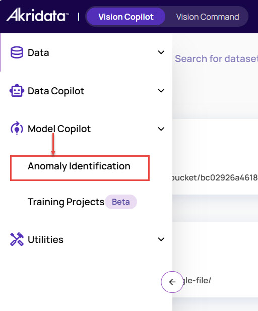
In the Anomaly Models screen, click New at the top-right corner to create a model project.
.jpg)
In the Create Anomaly Model window:
Enter Name and Description.
Under Clone from, you can select an existing model to clone the images and edit as needed.
.jpg)
Click Submit.
Upload good non-anomalous images and test images for the model training.
You can upload images from your local system or import images from the catalog.
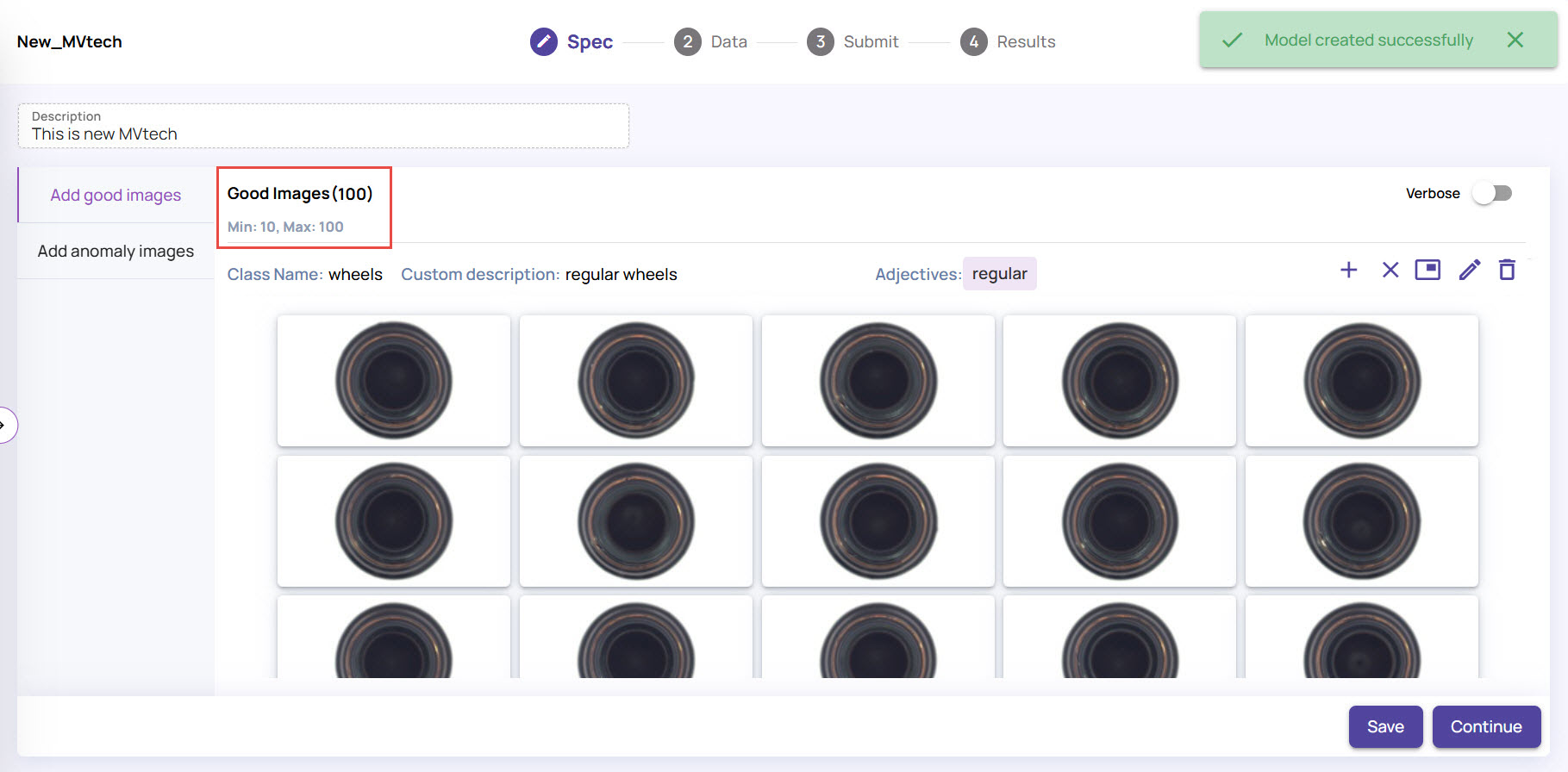
Under the Spec tab, click the + (plus) icon on the right-hand side, and click Upload Images.
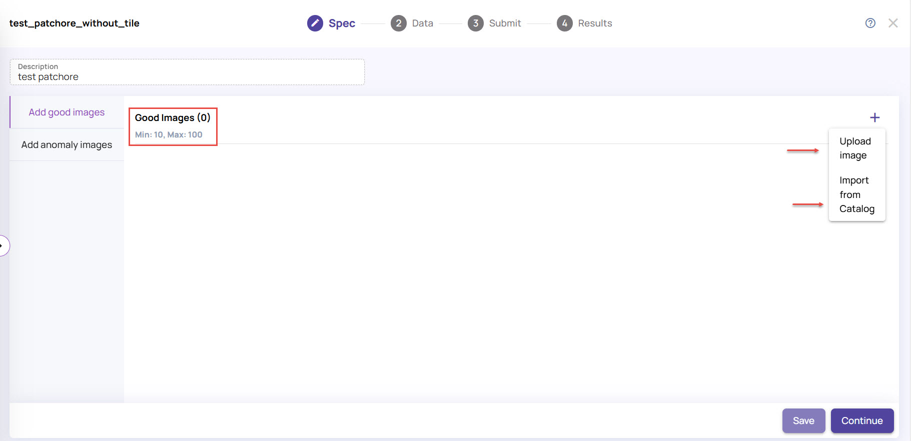
You can upload a minimum of 10 and a maximum of 100 good images. If you select more than 100 images for upload, only the first 100 will be uploaded.In the Upload Images screen, under the Add object name tab:
Enter the Object Name to identify the object in the images on which the anomalies will be detected. For example, if cracks and smudges on glass are the anomalies of interest, the object name must be specified as ‘glass’.
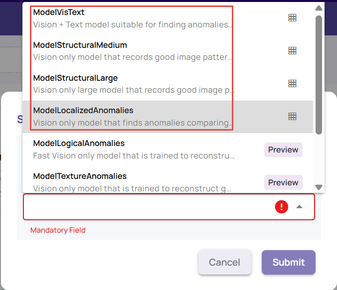
For a model that uses text inputs(ModelVisText), enable the Advanced options and add Adjectives that define the characteristics of a good image.
.jpg)
The adjectives are used to derive the description of the object. You can additionally provide a Custom description that best describes the characteristics of a non-anomalous object. Once done, click Next.
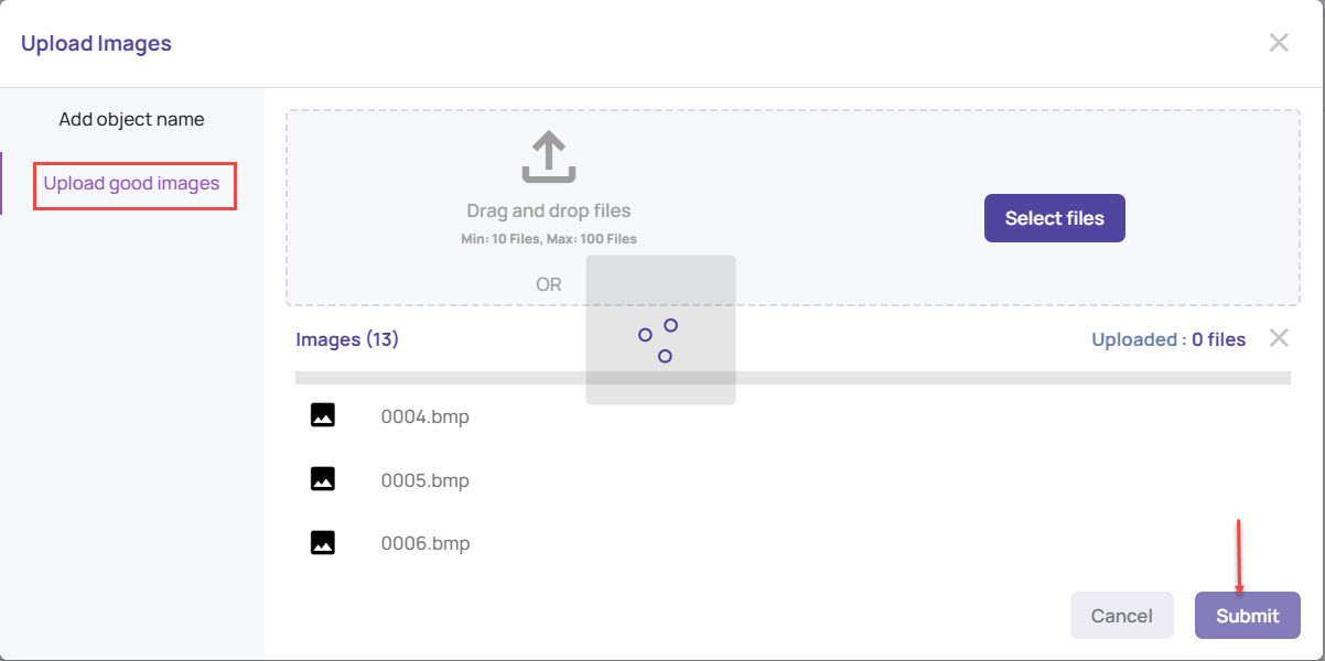
Under the Upload good images tab
Browse to the folder location and select the good images. You can view the progress of uploading the images.
Once the images are uploaded, click Submit.
Click Ok to get the good images.
If you need to add more images, you can click the + (plus) sign again to add more, as needed.
The next step outlines the process for uploading anomaly images. Uploading anomaly images is optional.
Under the Spec tab, upload anomaly and mask images, or query the catalog if needed, to support better analysis and more accurate anomaly detection. However, this step is not mandatory.
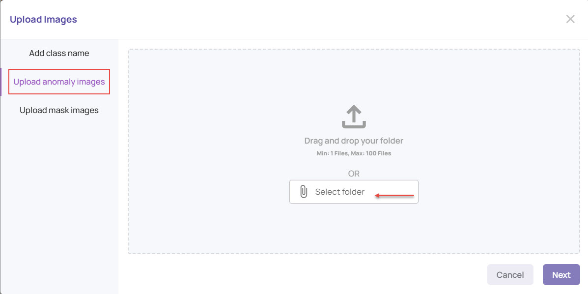
Click Add Anomaly Images and add the defect class name.
.jpg)
Click Next and Upload anomaly images.
Specific models(ModelSegmentGT) benefit from the presence of anomaly masks. Upload the mask images, following the same steps as above. The mask image format must be as follows.
The file names of the mask and anomaly images must match.
The file must be a greyscale PNG file with pixel values of 0 representing a good pixel and 255 representing an anomaly pixel.
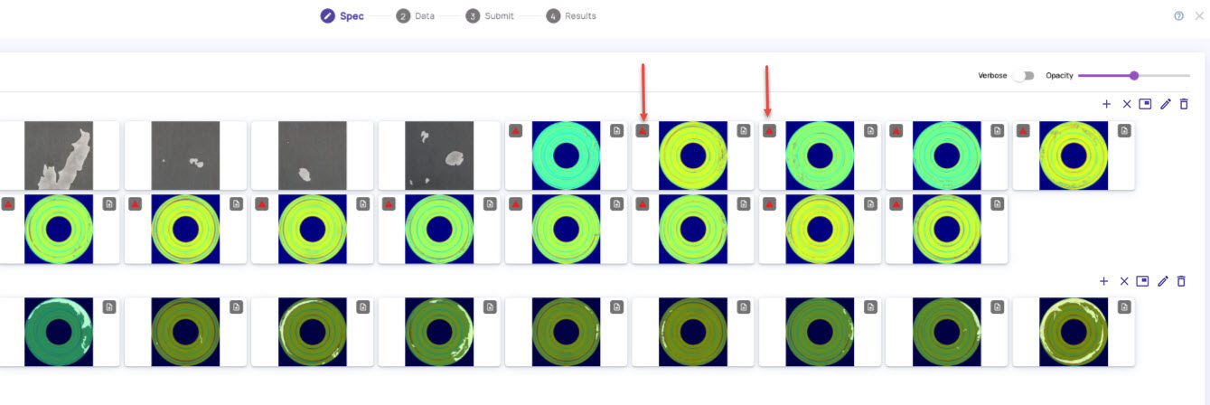
In case an anomaly image does not have a corresponding mask image, you can draw a polygon on the anomaly image after upload. Any anomaly image with a missing mask image is indicated with a red dot, as shown.
Click the rectangular icon adjacent to the pen icon on the top-right corner to draw the Region of Interest (ROI) where anomalies must be detected.
.jpg)
Static Polygon: Allows you to draw a polygon as Region of Interest. In this option, the same ROI is applied to all the images, including good and anomaly images. In the Draw region of interest screen,
Double-click at a point to start marking the box.
Click at different points on the image to form a polygon that defines the area of interest, as shown below.
Double-click to stop and close the polygon.
.jpg)
The same segment will be applied to all images, indicating that anomaly detection will now occur within the bounding box, i.e., the region of interest.
Use model: This option allows you to use the ROI from the already executed Training Models and run the anomaly detection.
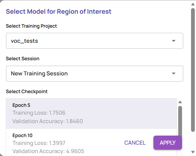
Select the training project from the list of successful projects.
Select the sessions from which you want to capture the ROI.
Select the checkpoint for Epoch, and click Apply.
Based on the setup in the training project, the ROI will be applied to the images being used for anomaly segmentation.
To remove an image, select the image, click the Cancel mark, and click Remove Image.
.jpg)
The image gets removed from the set. Similarly, you can click the delete icon in the top-right corner to delete all the images.Click Save > Continue.
Under the Data tab, click the + (plus) icon against Test Images, and click Upload Images. You can upload a maximum of 10000 images.
.jpg)
The anomaly model will be run on the test images to provide sample results for review and further action.
Once the images are uploaded, click the Verbose icon to view details for the uploaded images.
Click Continue.
The project screen displays the images in the respective sections, one after the other: Good Images, Anomaly Images, and Test Images.File Types
GIF and DCIM file types are not supported.
.jpg)
Review the images, and click Submit.
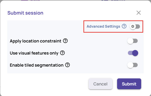
In the Submit session window, specify a few parameters that will be used to decide a suitable model.
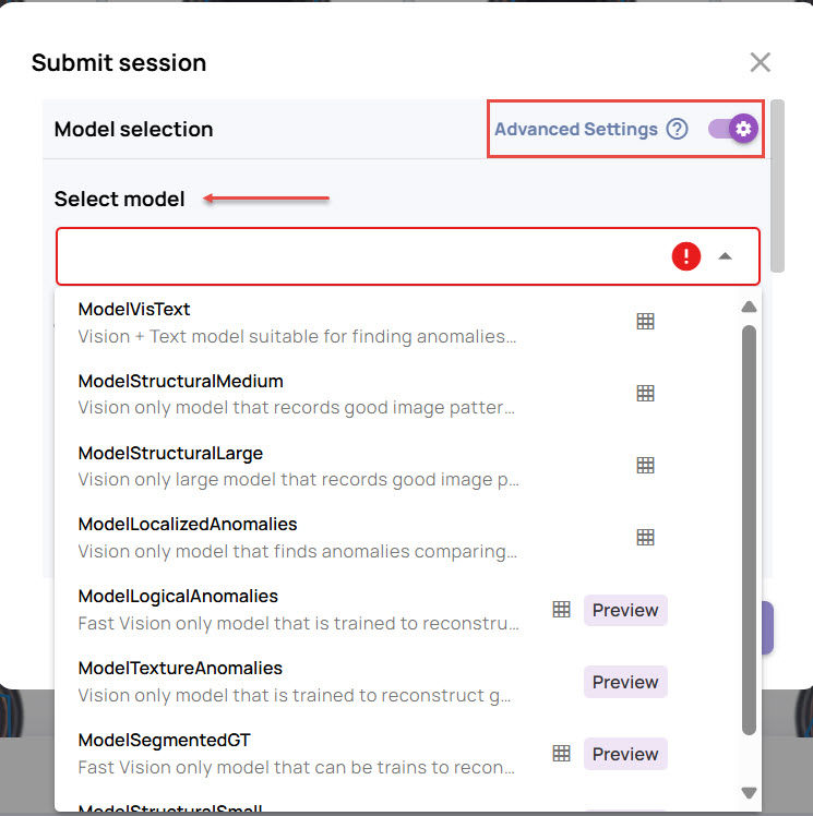
Select model: Enable the Advanced settings if you want to select the model based on which the anomaly results should be populated.
Apply location constraints: Enable this if the anomaly is expected at the exact location in every image.
For example, if all good images have a spot on the top left corner of the image and the test image has a spot on the bottom right corner of the image, then with location constraint applied, this will be flagged as an anomaly since the top left corner of good images is different from the top left corner in the test image.
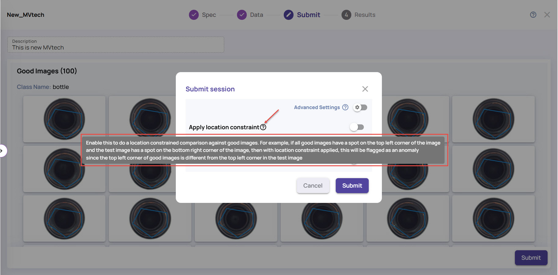
Hover the mouse on the question mark (?) icon to view the tooltip.
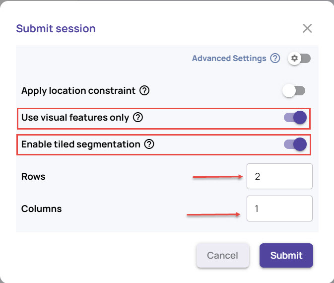
Use visual features only: Enable this option to ignore any textual information, such as Object name, in the image during detection.
Enable tiled segmentation: Enable this option if you have extremely fine anomaly artifacts or have high-resolution images. The procedure divides the image into a grid of tiles and runs the anomaly segmentation model individually on each tile.
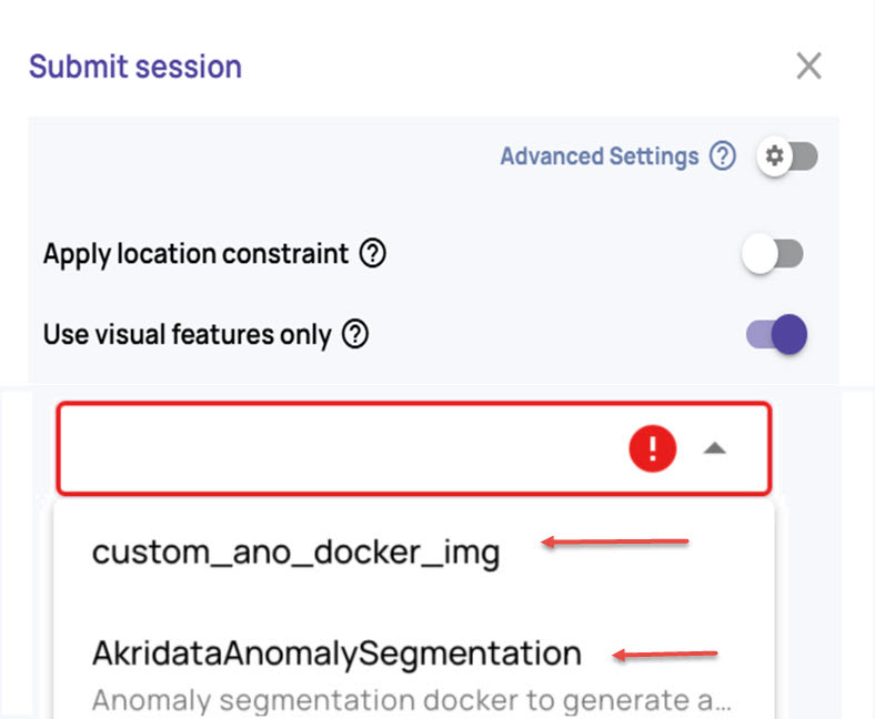
In case you have created your own docker image for anomaly segmentation, select the docker image
Allowing the system to select a model is preferred, but for advanced use cases, you can choose the model explicitly. To do this, enable Advanced Settings.
Select a model from the list.
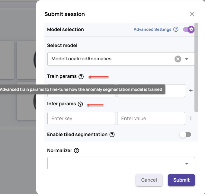
Enter the Train params and Infer params with the corresponding values, if needed.
Param settings for advanced users
Train params: Enter advanced train params to fine-tune how the anomaly segmentation model is trained.
Infer params: Enter advanced infer params to fine-tune how anomalies are inferred.If you select a model with tile segmentation, use Enable tiled segmentation and specify the parameters, if needed.
Under Heat map settings, set the Heat map size, as needed, and the Heatmap smoothness factor.
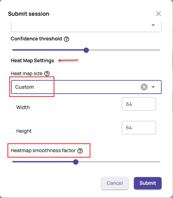
If you choose Custom, you can set the heat map's width and height. Alternatively, you can select Auto to have the system set the heat map size automatically.
Click Submit.
This initiates an anomaly segmentation model training session, followed by generating inference results on the test images. Depending on the size of the test image set, the anomaly results may be displayed in a few minutes to hours.
.jpg)
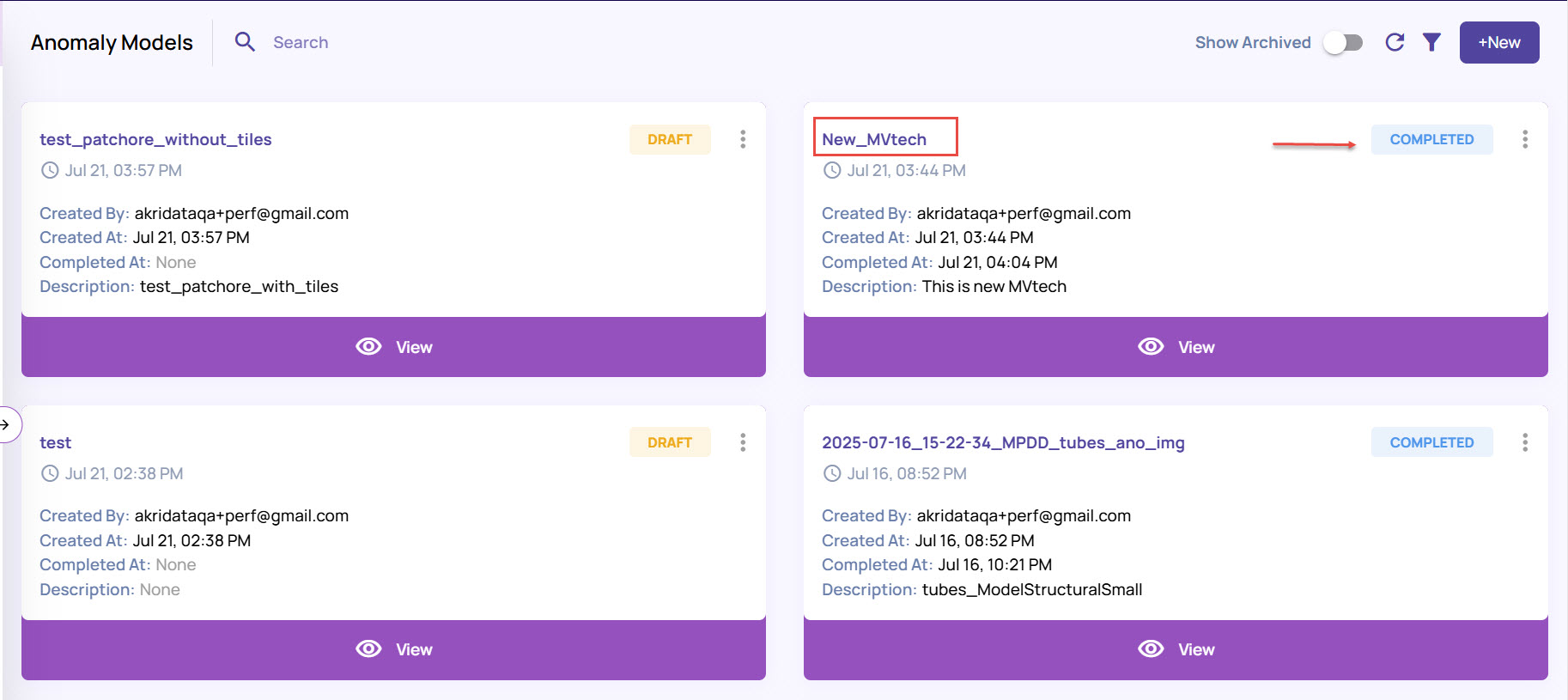
Once the model is created, it will appear in the Anomaly Models page, displaying the creation details, as shown.